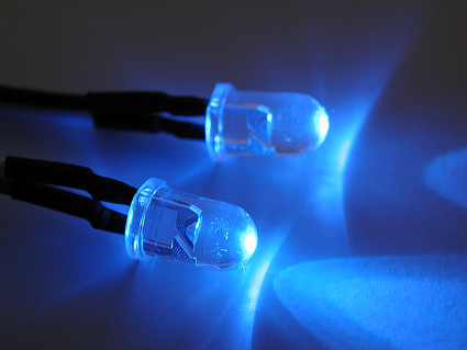
 This is the Light Show made from LEDs and few discrete components like resistors and transistors. It transforms audio signal into light signal with LEDs. We have used two types of LEDs, white and blue, each one for different sound channel (from stereo audio output).
Our prototype was first built on solder-less breadboard. Link to YouTube video
Components that are required for this build:
– 5 VDC regulated power supply (You can use your USB cabel)
– 2 NPN transistors (any transistors will work, we have used BC547 for our prototype) (for one channel)
– 1x300K resistor and 1x33K resistor (for one channel)
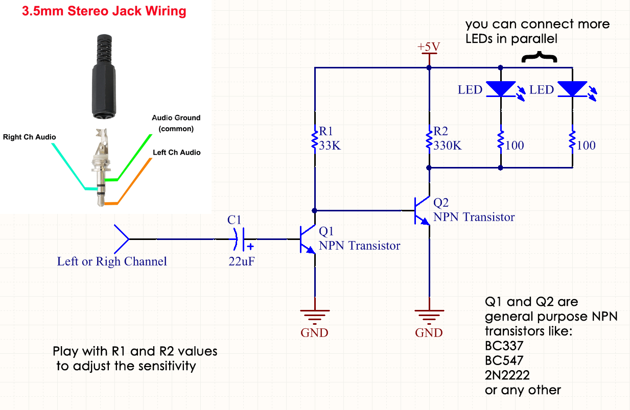
Connect the components like in the schematic displayed below and you should have your very own led light show that flashes in rythm of you music. Cool right?
But don’t stop there, one of the things you could do is create a case for your light show, use even more LEDs (you would need better power supply since USB has 100mA max output), use high-power LEDs and etc.
We would greatly appreciate if you could spare a minute of your time and let us know what do you think about it, did you manage to assemble it on your own, do you need help or do you have suggestions for future projects.
Enjoy!
Here is the short video of LED light show in action
And here is the schematic.
Connect positive side of your LED to the D+, then, negative side of your LED to the one side of the resistor and then other side of the resistor to the D-.
If you wan’t to use USB cable for power supply, VCC or 5V is red wire from your USB cable
I’m using blue and white LEDs with 3V forward voltage and 20mA current, so the resistor for them is about 100 ohm, if you intend to use other type of LED, you will have to calculate resistor values for you VCC and diode forwarde voltage.

** update **
Here is the “updated” schematic since lot of people still ask for this schematic and how to wire the circuit.
can u help me with the circuit. in don’t actually understand urs schematic diagram ….im planning to make this on my final project….
How can I help you? What don’t you understand about the circuit? If you know Electronics 101 it should be really simple for you to understand.