Let’s see how we can build a simple WiFi enabled 3D printing filament diameter sensor. After finishing this project, I can say it was a lot of fun for me. But before you do the same, check out the video and ask yourself if you *really* need this sensor?
Leave a CommentTag: pcb
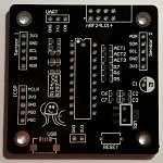
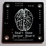
These PCB-s are a part of much bigger project that I am currently working on and I have been waiting for them waaaay too long. Boards are designed to house two I2C sensors, (almost any I2C sensor breakout board can fit onto dedicated headers), at the moment I am using Temperature+Humidity sensors, Pressure Sensors, Ambient Light sensors and few others on these boards. Also I am using PIC16F1829 microcontroller to do all the “magic” and nRF24L01+ for communication with the main unit that does storage, data analysis and communication with other parts of the project.
2 CommentsUSB Power supply Active Load Tester or short PAL Tester is unit designed for testing the quality of the power supplies.
Idea was to create low-cost, precise device for simultaneous measurement of Voltage and Current drawn from the device under test. This is one of my weekend projects that I have decided to release to the public. All source files can be found on projects GitHub page.
Device Features:
- Open Source and Open Hardware
- Modular design, easy to understand and change/adapt to your needs
- Uses widely available and off-the shelf components
- Components Bill of Material is below $10
- Integrated USB-to-Serial converter for easier interface with the device
- API for communicating with PC
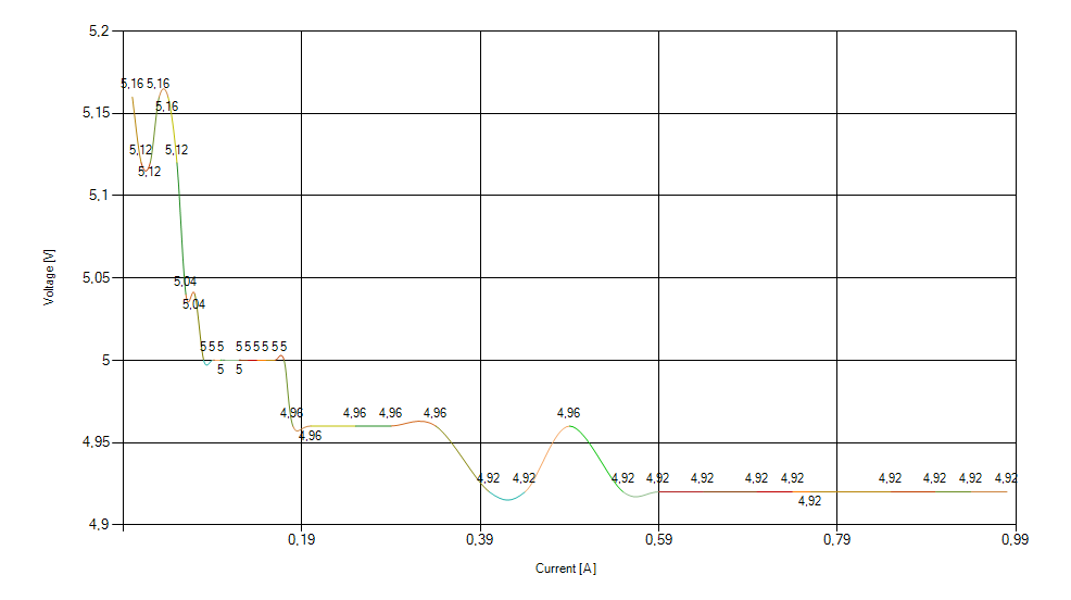
- Recording Voltage vs Amps data and graphing the results
- Easy to use
 I’m working on a new weekend project that will be released as soon as I finish the Windows application and it will be released as open-source open-hardware project. The uber-cryptic title stands for “Power-supply Active Load tester”.
Recently I was in need for a simple device that will draw reasonably precise amount of current from my power supply unit under test and read the voltage and current draw. There are a lot of schematics and products that do just that, or you can do this just with two digital multimeters, op-amp, mosfet and potentiometer and that will probably work just fine, but I wanted to create my own version and try to improve it. 🙂
Heartbeat key-chain is intended to be a small gift that your loved one can carry with her/him wherever she/he goes.
Basically top side of the PCB is touch sensitive and has one RGB LED. When the exposed copper on the top side is touched, the microcontroller detects it and begins to pulse the LED in the heartbeat like pattern.
Bill of material, schematics and source code are available on GitHub.
I am posting render images of the PCB since I’m waiting for the Fab house to manufacture the boards for me.
2 Comments


