USB Power supply Active Load Tester or short PAL Tester is unit designed for testing the quality of the power supplies.
Idea was to create low-cost, precise device for simultaneous measurement of Voltage and Current drawn from the device under test. This is one of my weekend projects that I have decided to release to the public. All source files can be found on projects GitHub page.
Device Features:
- Open Source and Open Hardware
- Modular design, easy to understand and change/adapt to your needs
- Uses widely available and off-the shelf components
- Components Bill of Material is below $10
- Integrated USB-to-Serial converter for easier interface with the device
- API for communicating with PC
- Recording Voltage vs Amps data and graphing the results
- Easy to use
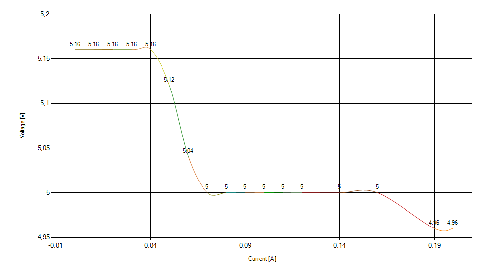
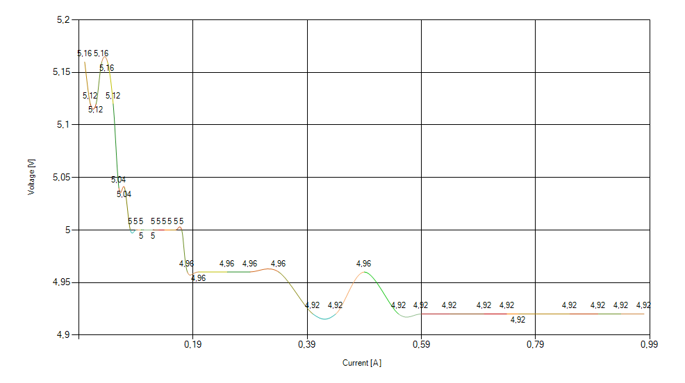
Example plot of Voltage vs Current for 5V 1A adapter
Basic capabilities:
- PSU under test max voltage 55V
- Current Load of 5A (or more by changing Rs value)
- Current and Voltage measurement accuracy is below 5%
Component list and estimated price:
- 1x – PIC16F1829 [$1.6]
- 1x – MCP6002 Rail-to-Rail OpAmp [$0.69]
- 1x – MCP4726 12bit DAC [$0.96]
- 1x – IRF L3705 Logic Level N-MOSFET [$0.5]
- 1x – CH340T USB-to-Serial converter [$0.99]
- 10x – 1 ohm 1% 1/2W resistor
- miscellaneous (resistors and capacitors)
How to build your own USB Power supply Active Load Tester:
If you are going to use photo etching or toner transfer method to make DIY board, there are bottom layer printouts in the Hardware folder that are ready for you to print and create a board via your favorite PCB manufacturing technique.
Once you have finished with developing, cleaning and drilling the board, in Hardware folder you have a file “Component-placement.png” which shows how and where to position components.
If you want to make changes or review the design, Schematic files (in .pdf) and Altium project files are available for download in Hardware folder. Open the design files in Altium or convert them to your favourite CAD and edit them.
Device operation for laymans:
The microcontroller sets the voltage on the positive input of the Op amp through a Digital-to-Analog converter (DAC).
The output of the op-amp then drives the N-MOSFET that allows current to flow.
The negative input of op-amp is connected to the sensing resistor (Rs) that is between the source of the N-MOSFET and GND.
The voltage across Rs (and thus voltage on the negative input of th eop-amp) is proportional to the current flowing through the resistor. For 1 Ohm resistor, V=1 ohm x Current draw.
Since an op-amp “tries to equalize positive and negative inputs”, suppose the voltage on its positive input is 1V. To equalize positive
and negative inputs, the voltage on the negative input (the one that is connected to Rs) must also be 1V, so the op-amp drives the N-MOSFET to open, allowing the current to flow, but only enough to make 1V on the negative input. Calculating the current draw from the above mentioned formula, we see that in this example, the current draw will be 1A.
Development
Want to contribute? Great!
Currently there is a C# .NET application written for interfacing with the device. It works but it’s very rough and very basic. If you are interested in writing an application in Python, C++, C or any other language, please do. I would greatly appreciate that. Also if you need help or more information feel free to contact me over Skype, Email, IRC or whatever way you like. 🙂
Also if you think you can help in any other way, please do. Any kind of help is greatly appreciated.
Special thanks to
– Loshki from #electronics @ Freenode
– Your name here 🙂
License and Disclaimer
You are using this software and hardware at your own risk.
Open Source, Open Hardware. Do WHATEVER your want 🙂
If you like this project, let me know in the comment section below, share it with your friends and tell me what would you like to see next.
[…] USB power supply active load tester – [Link] […]