Making a IoT LED dimmer that you can control via your PC, phone, tablet or any other device connected to the network is super simple, and I’m going to show you how.
I’m sharing my three channel LED dimmer that you can use to dim single RGB LED strip or dim three separate LED channels. I want to be able to control lights above my desk and also mix warm white and cool white strip to give me more flexibility over lighting while I’m working, taking pictures or watching movies.
This is going to be a very short and very simple project that if you follow steps below, you can build it in an hour (excluding lead time for components).
For this project you will need:
- LED strip (RGB, or 1/2/3 single color LED strip)
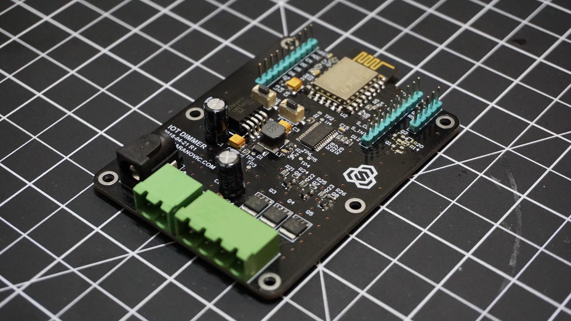
- NodeMCU (ESP8266 dev board)
- Three N-Channel Power MOSFET
- Three N-Channel Signal MOSFET
- 12V Power adapter for LED strip
Firmware
When it comes to writing the firmware for ESP8266, there are tons of options. To keep things simple and in effort to save time, in this example we’ll use Arduino since it has plenty of libraries, example code and it’s easy to understand if you are just trying to get your feet wet with custom hardware.
Let’s take a look at the whole Arduino sketch, and then just go over some lines that might be of interest to you. The code provided should be pretty much self-explanatory and also comments should come in handy.
At minimum, you should modify following lines to get our IoT dimmer connected to our WiFi.
// WiFi Configuration (hard-coded at the moment)
static const char ssid[] = "__Your-WiFi-SSID__";
static const char password[] = "__Your-WiFi-Password-Here__";

// mDNS hostname for this device
// You should be able to call http://dimmer.iot
static const char dns_hostname[] = "dimmer";
I am not planning renaming my WiFi network or changing password on a daily basis so this is fine for me. (If you want, you can download Arduino libraries that allow you to set NodeMCU in station mode so you can connect to your device, configure which credentials you want it to use and then it will restart in client mode and try to connect to you WiFi access point.)
Also whatever you set as `dns_hostname` you should be able to connect to your IoT dimmer by typing in http://dns_hostname.iot, in my case that is http://dimmer.iot. It is more convenient than IP but this may or may not work for you, depending on your network config.
Arduino code is pretty “boring” and “nothing special” in code is happening, at least on the surface that is.
Sketch code is pretty self explanatory, set LED intensity, handle URL request, handle websocket request and that’s pretty much it so we won’t waste too much time on it.
Hardware
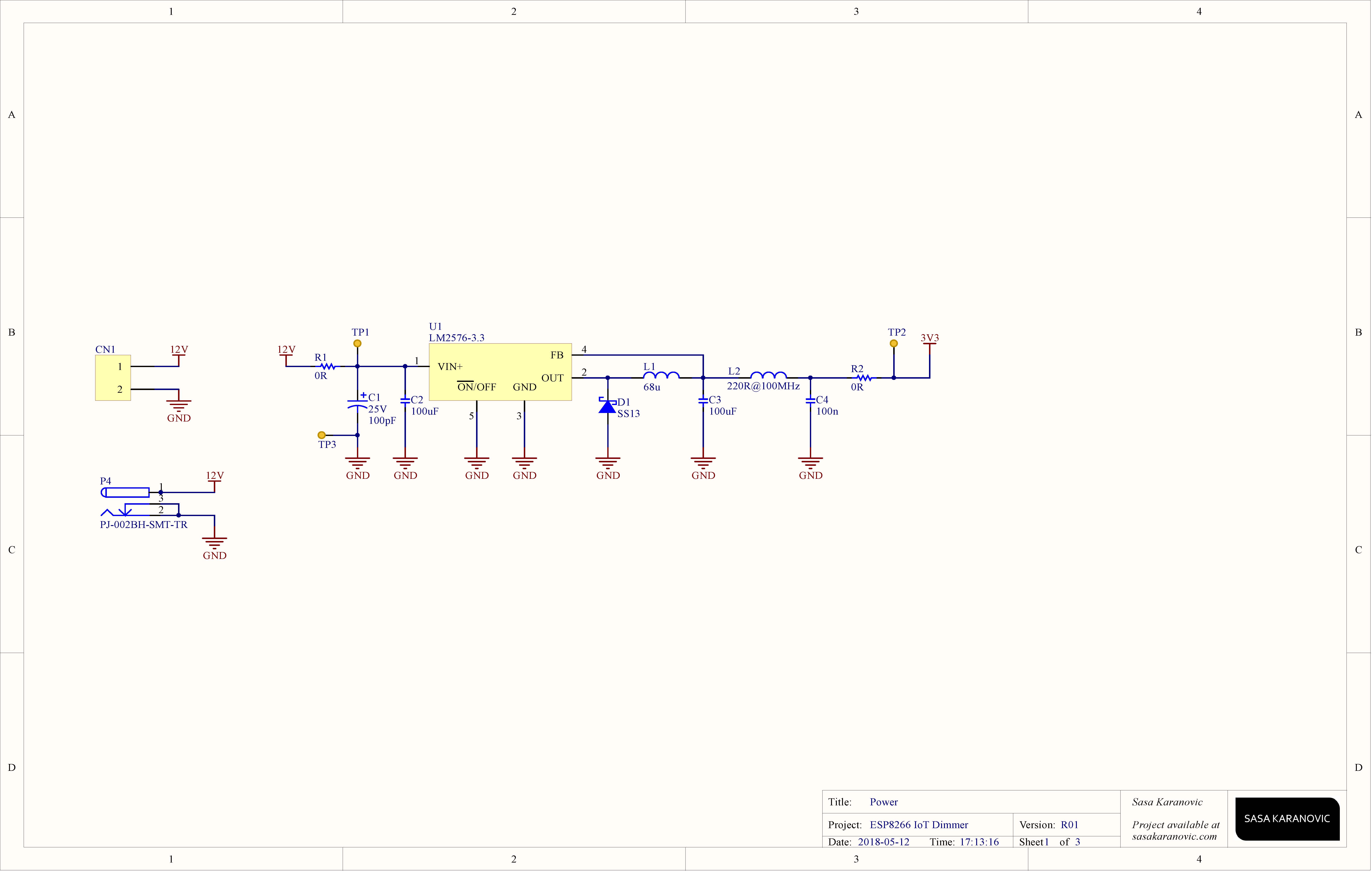

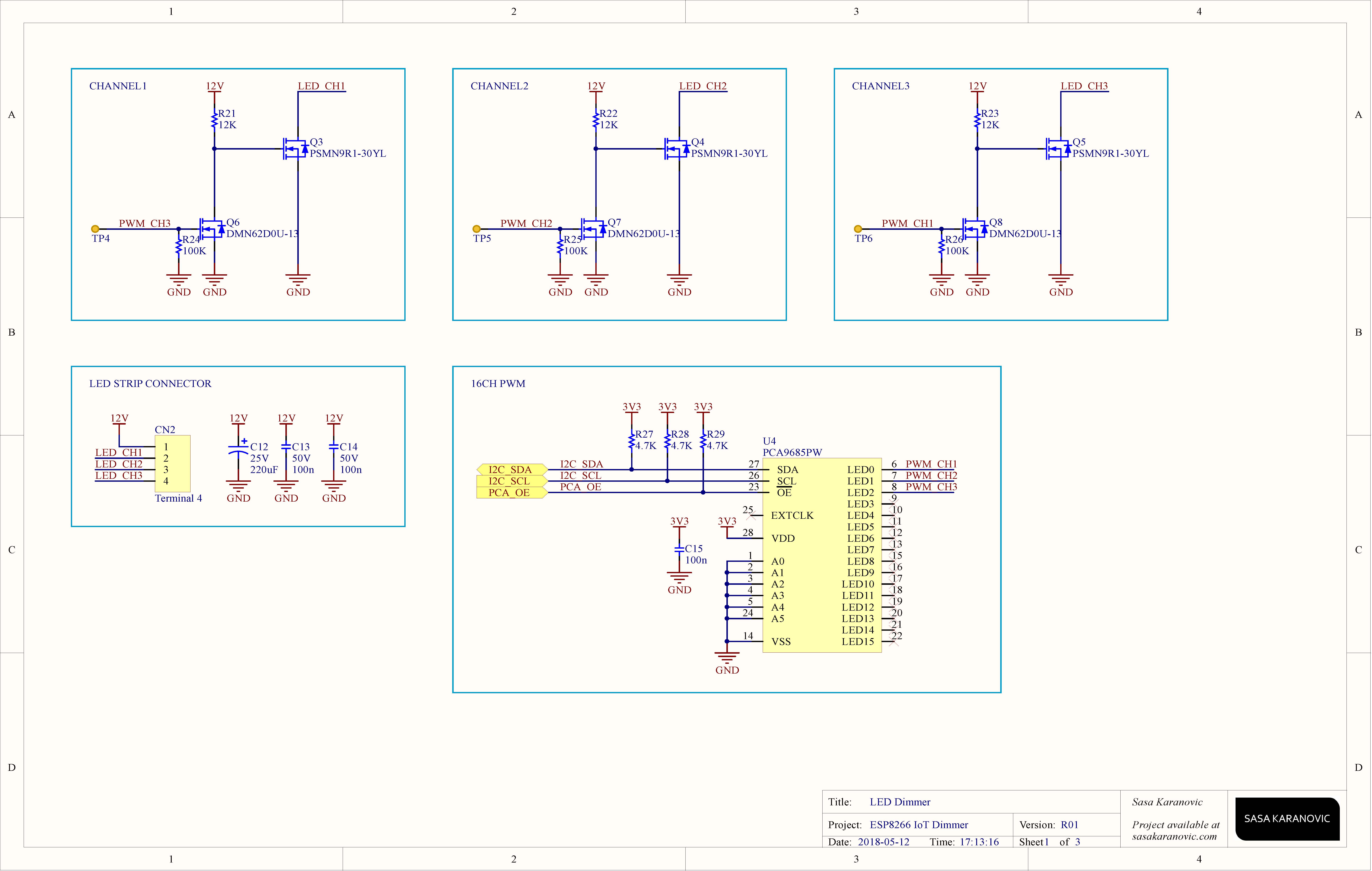
ESP8266 board already comes with pretty much everything we need. We just need to add drivers for our LED strip. For that we are going to use N-channel power MOSFETs.
We expect that our LED strip is going to draw several amps of current, that means that we have to be careful with our LED driver so it doesn’t get too hot or burn. Power dissipated by a MOSFET can be calculated as
P=I2RDS_ON
P – Power dissipated by mosfet
I – Current through MOSFET (and also through LED strip)
RDS_ON – On resistance of a MOSFET (specified in datasheet)
Brightness of our LED strip will directly depend on current trough it. So to reduce power dissipated, we want to keep RDS_ON as low as possible. RDS_ON depends on voltage between Gate and Source (VGS). So we want to select a MOSFET that has low RDS_ON and can handle voltage of our LED strip (12V).
See it in action
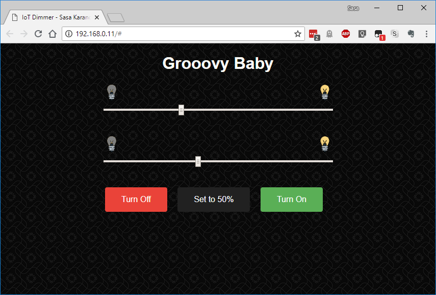
By opening your favorite web browser, you can either type the IP address of ESP8266, something like http://192.168.0.11, or you can type http://dimmer.local and it will try to find ESP8266 on your network. You will be greeted with a web page that we designed previously in Firmware section. That’s it, you can now control your LED strip(s) through your PC, mobile, tablet or any other device that has a web-browser capabilities. Also since we are using websockets, if you have more than one client connected to IoT dimmer, any change is immediately propagated to everyone.
Update: I’ve been using this IoT Dimmer for about three months now and I’m thrilled with how it works and performs. Also it’s a great conversation piece when I have guests over.
How to make it cool and work for you?
Controlling LEDs through your web browser, mobile, tablet and etc. is fun, but how can you make it even more cool? Here are few suggestions for improvements (some of which I’m using right now):
- Automate it with Python
My Dimmer is controlling two channels of warm and cool white LEDs that sit right above my workbench. So I have a tiny Python script that runs in the background and if I’m watching a movie it will dim the lights. If I’m working on a project, it will increase brightness and if it’s late at night, cool white channel is slightly dimmed to reduce blue light. - Make it talk with Google Assistant / Alexa / _your-favourite-assistant -name_here
You have dimmer that sits on your local WiFi network and it’s using websockets to receive commands and sync clients. It is pretty straightforward to make your favorite home assistant talk with your dimmer so you can use your voice to control the lights. - Automate it with IFTT or your other favorite service
You can use IFTT (for example) to send commands to your dimmer based on your Android/iPhone location. Automate it based on time of day. Or pull data from another sensor (like ambient light sensor) and based on data turn LEDs on/off.
Source files
Schematic, manufacturing files and source-code can be found in my ESP-IoT-Dimmer GitHub repository.
Feedback
Please let me know what do you think? Did you find this project interesting and easy to make? Would you like to see more complex projects and if yes, what type?
If you made it, please share your results and don’t be shy, leave a comment below!
Thank you for sharing this! Any chance there is a BOM available too?
You’re welcome! Absolutely, I’ll add it to GitHub repository.
Edit: Added.
Hi
Nice project. Wanting to do something like this.
I want to etch my own board. Can you please share the eagle cad files or a pdf would also do.
Thanks
Thank you. This is a open-source open-hardware project, so all source and design files are available inside IoT LED Dimmer GitHub repository (https://github.com/SasaKaranovic/ESP-IoT-Dimmer)
[…] IoT LED Dimmer – [Link] […]
Hi, it is very impressive. i just want to know to control it using MQTT. is it possible? what are the amendments in the code for that purpose. thanks.
Thanks!
You can definitely modify it to use MQTT instead of webserver/websocket. Obviously you would need to set-up a MQTT client and then set-up triggers and message parsing in your code.
I’m sure you can find many examples on using MQTT and then modify one of them to control LEDs. Let me know how your finished project looks like.
Cheers!
Hi,
is there any particular reason that this dimmer is only 3 channel? Looking over specification of the PCA9685PW,118, this dimmer could be for 16 channels, right?
Thanks,
Simon
Hi Simon,
You are right, you could add up to 16 channels if you want/need to and drive them directly from PCA9685 IC.
In my case this was an overkill so I used one channel for warm white strip, another for cool white and left the third one for future proofing (haven’t had the need for it yet).
Strobe function with adjustable frequency would make this perfect!!
I assume you should be able to add strobe function to the code. Everything is open-source, open-hardware so feel free to contribute or modify the design to best work for your use case.
In the original version, I did not add strobe light function since working/designing under a strobe light isn’t that enjoyable, at least not for me. 🙂
can you make sous vide project using esp8266? :)). Thank you
This one is using ESP8266? Are you suggesting I make a video about it or maybe use an ESP32? 🙂