See it in action
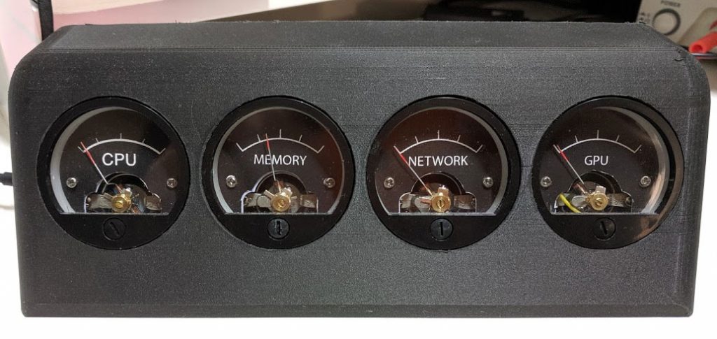
In the video above, you can see first a power up sequence where all four dials go from zero to 100% and back to zero after which they start showing real time CPU, Memory, Network and GPU usage. After that we run a internet speed test to show how the real-time information is displayed on the dials.
Project update
I am very pleased to announce that this project has turned into a product!
Thanks to collaboration with Streacom, you can now purchase VU Dials.
Intro; Why it took so long to write about this
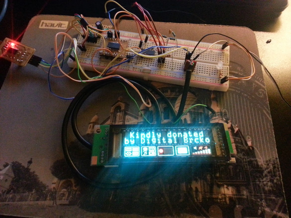
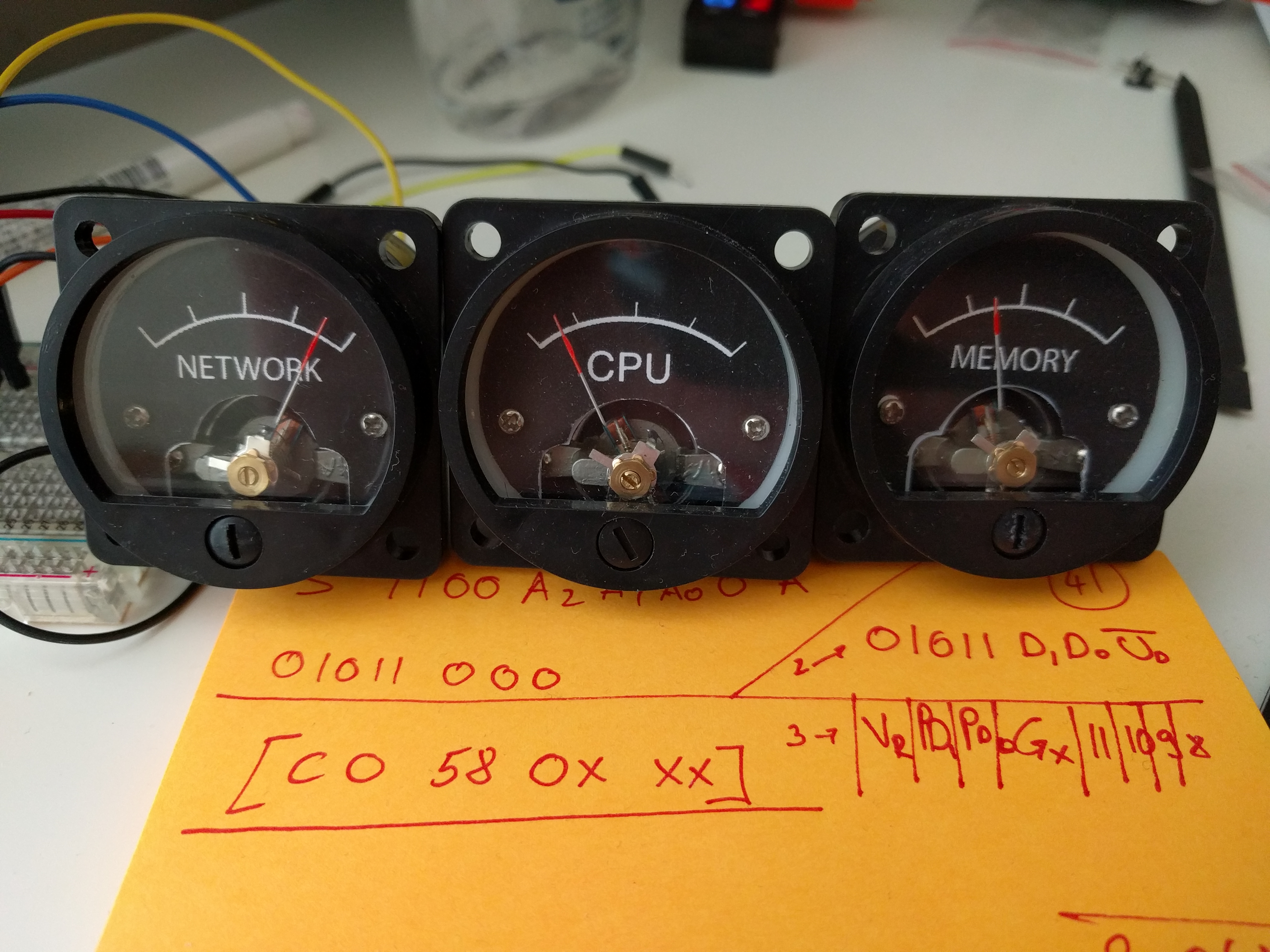
As I mentioned, I’ve been playing around with this idea for a while and by looking at some of my notes, the idea of having a physical resource monitor for my PC dates years and years back (see images at the end for some early on prototypes that I was able to dig up).
Since I unfortunately can’t publicly write about the awesome projects I get hired to work on, I try to write about projects that I do in my own spare time and present them to my readers as DIY projects/guides. I take these very seriously and out of the respect to my readers who patiently wait for my next project post, thank you all for that very much, I try to keep the projects posts very detailed and provide every piece of information or files that you might need to build one yourself.
Because of that I’ve been pondering for weeks(!) how to present this project so that I cover it in a way that intrigues but doesn’t scare someone who isn’t familiar with electronics but wants to understand how every piece of the project works and then they can build their own or modify it, but also to go into fine grain details for those more experienced readers without scaring off or boring people off. Now with several draft and more hours spent writing about this than it took to actually build the entire thing… I still haven’t found the silver bullet but I decided that I’m going to just write something, and then based on your feedback I will either write another followup to cover a certain topic(s) that you liked, update this post with more information, provide more info in comments or on Twitter, update GitHub repository or who knows…
As always, all of the source files, design files and any other material you might need to build this project are provided after we explain how everything works.
In a nutshell, how does it work?
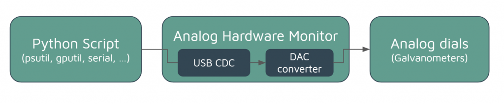
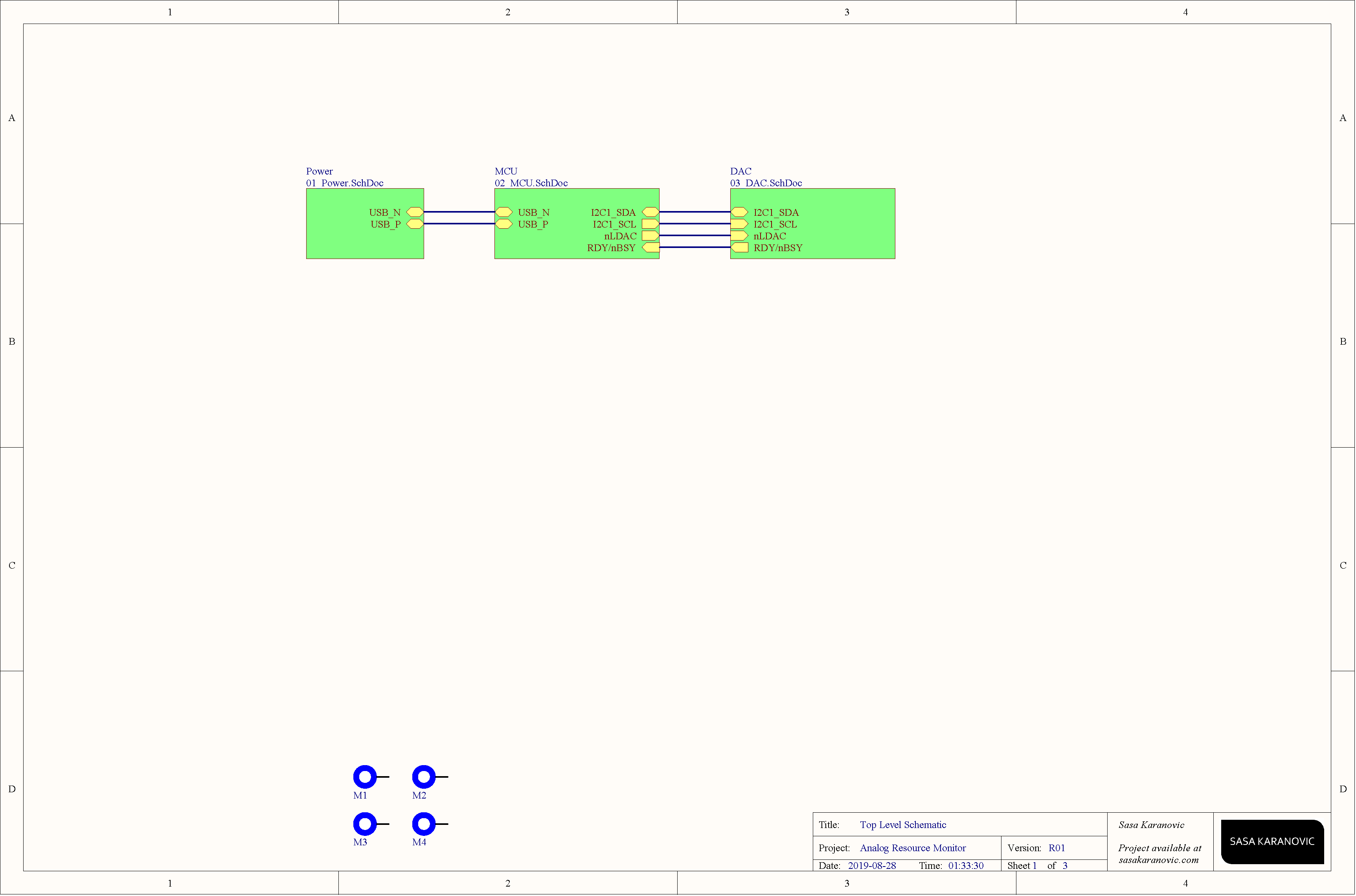
The overall architecture is very simple; There is a python script that is running on a PC and collects CPU, memory, network and GPU usage. Then, it sends that information over serial COM port to the hardware monitor board for processing. New voltage values are calculated and passed to the digital-to-analog converter (DAC) which drives analog dials (galvanometers) by applying a voltage that will move the needle to a desired location. Super simple but it get’s the job done.
Presenting the usage values and driving the analog dials
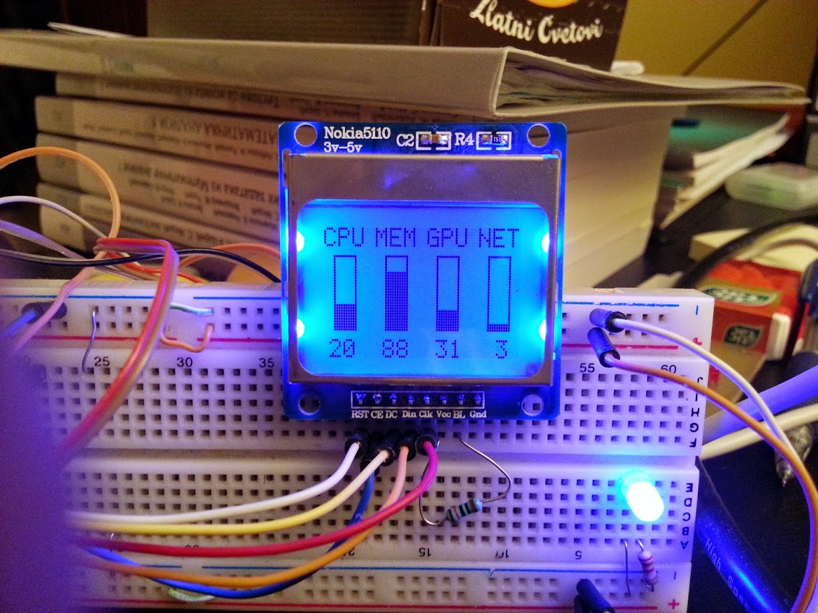
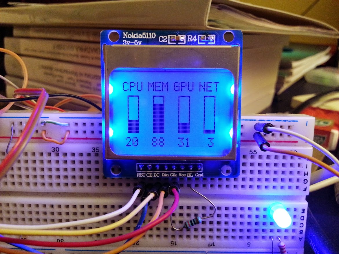
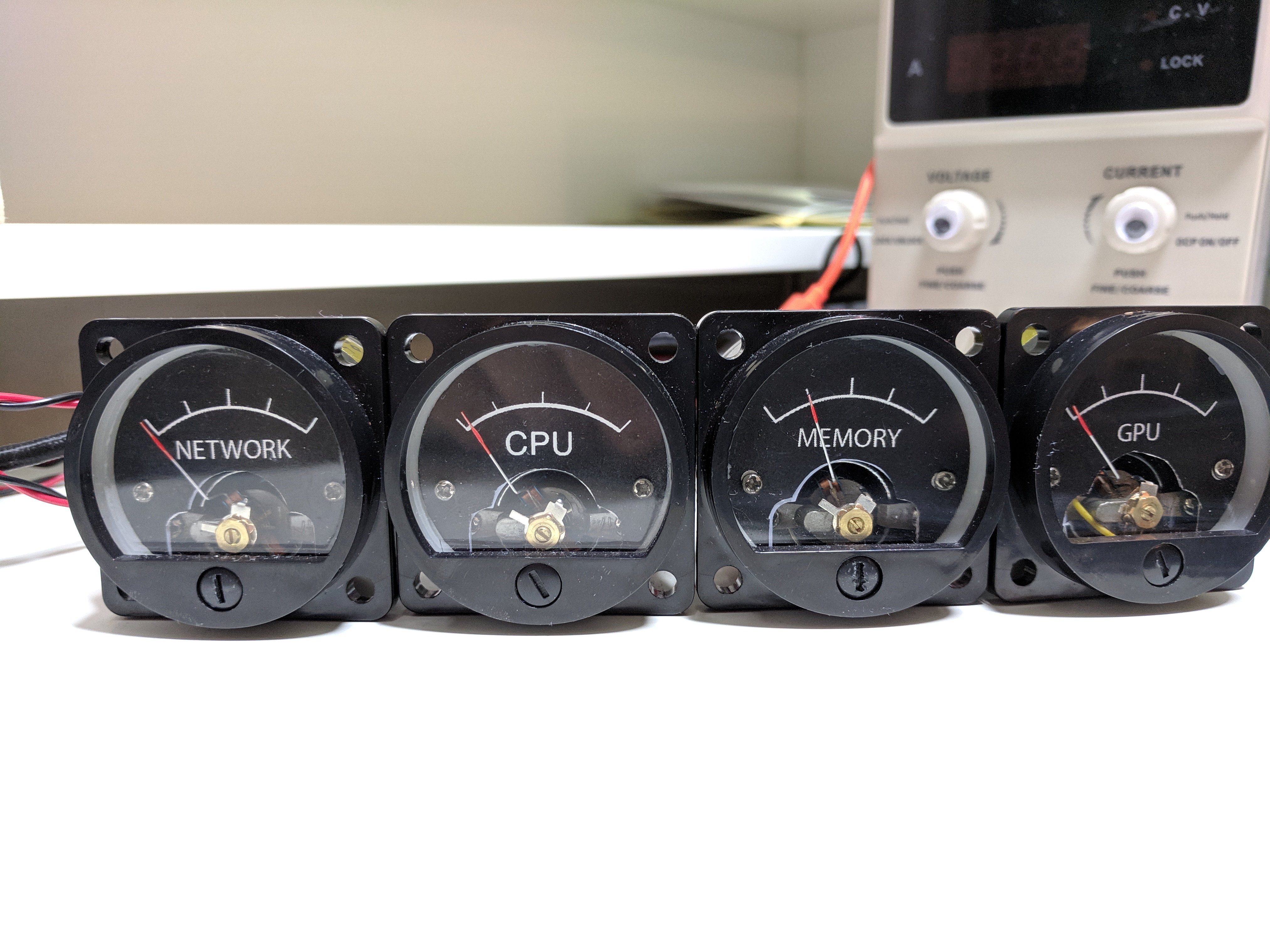
I’ve been experimenting with different ways to show this information, and while some earlier prototypes had OLED/LCD to show the usage information, it looked very fancy but it was missing something, after all what’s the difference between showing it on your monitor vs the OLED. But then I found my old galvanometers laying around. They are analog, they can show any value from 0-100 and also they produce, to me, a very satisfying audible *click *when your CPU/memory/network/GPU usage spikes up or down. Also they allow you to create a modern look or go full steampunk with some coloring and different enclosure, it’s up to you.
Now for the technical part, I will not bother you too much about the galvanometers and how they operate, there is a very nice Wikipedia page that explains this. For our purposes we can simplify it by saying that they will move/deflect the gauge needle proportional to the current that we are driving through it.
Since we want to use a simple microcontroller without any fancy driving circuitry, it’s desirable that we control the voltage instead of current. Most of you already know the Ohms law in form of I=V/R which states that current through the resistor will be equivalent to the voltage applied across the resistor divided by the resistors resistance.
Now we can add a fixed resistor in series with the galvanometers and by applying a known voltage we can calculate exactly what is the current going to be.
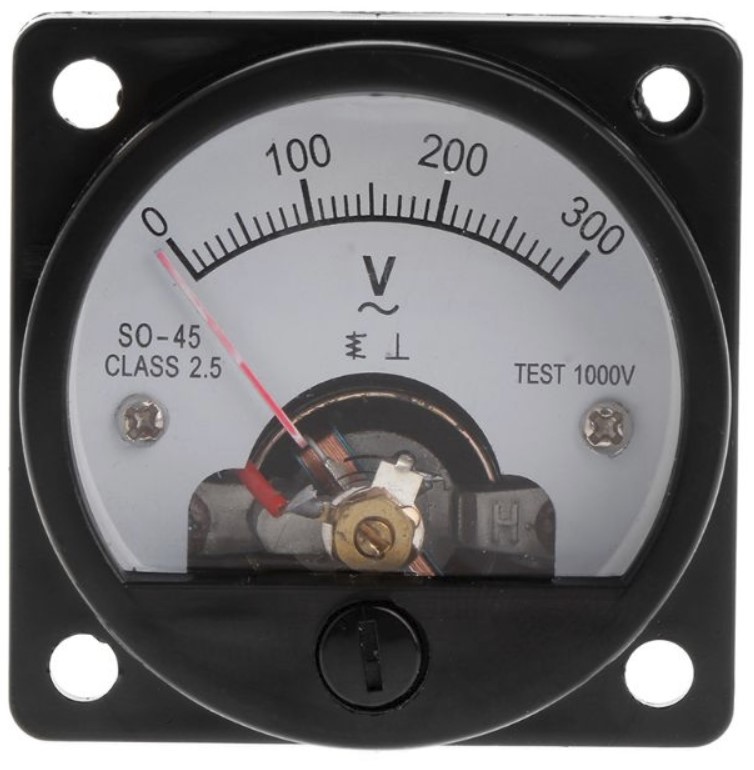
When you open your galvanometer, depending on it’s rating and scale, it will most likely have a diode, capacitor and a resistor inside. You can remove them completely since we are going to be driving them by a DAC (digital-to-analog converter) and a series resistor. Also while you have the galvanometer open, you might want to print and stick a custom face for your dial, see image below.
Your galvanometer will have a rating for full deflection (i.e. 2.5mA or similar), so you should select a resistor that gives you that current at your DAC’s max output. This will ensure that the needle can go all the way from 0-100.
Protoboards are nice but let’s make something nicer
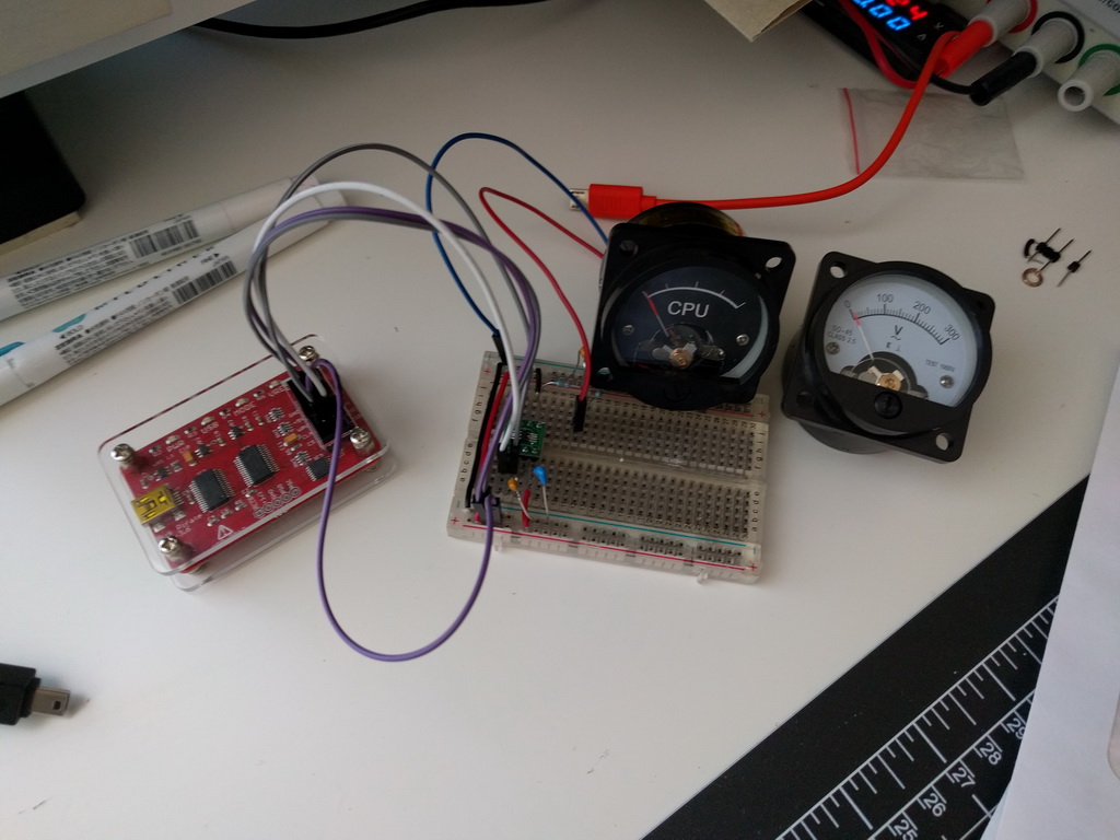
As you can see it’s possible to drive these analog dials with pretty much any DAC, as long as you can drive the DAC. In fact, for a while I had this set-up but with four analog gauges running on my desk for a while, being driven with BusPirate and MCP4728. Reason why I’m mentioning is to emphasize that you really can make this project with whatever you have laying around, wheater it’s a fully custom board like I did or with an Arduino, eval board, BusPirate, BluePill, ESP8266/ESP32 or any other board, really. If it doesn’t have a built in DAC, you can add an external one for few cents and you are good to go. Also if it doesn’t have USB support, you can add USB-to-UART IC. The component selection for my schematic was mostly influenced by what components I already had laying around, so you might want to select different one based on your preference or inventory.
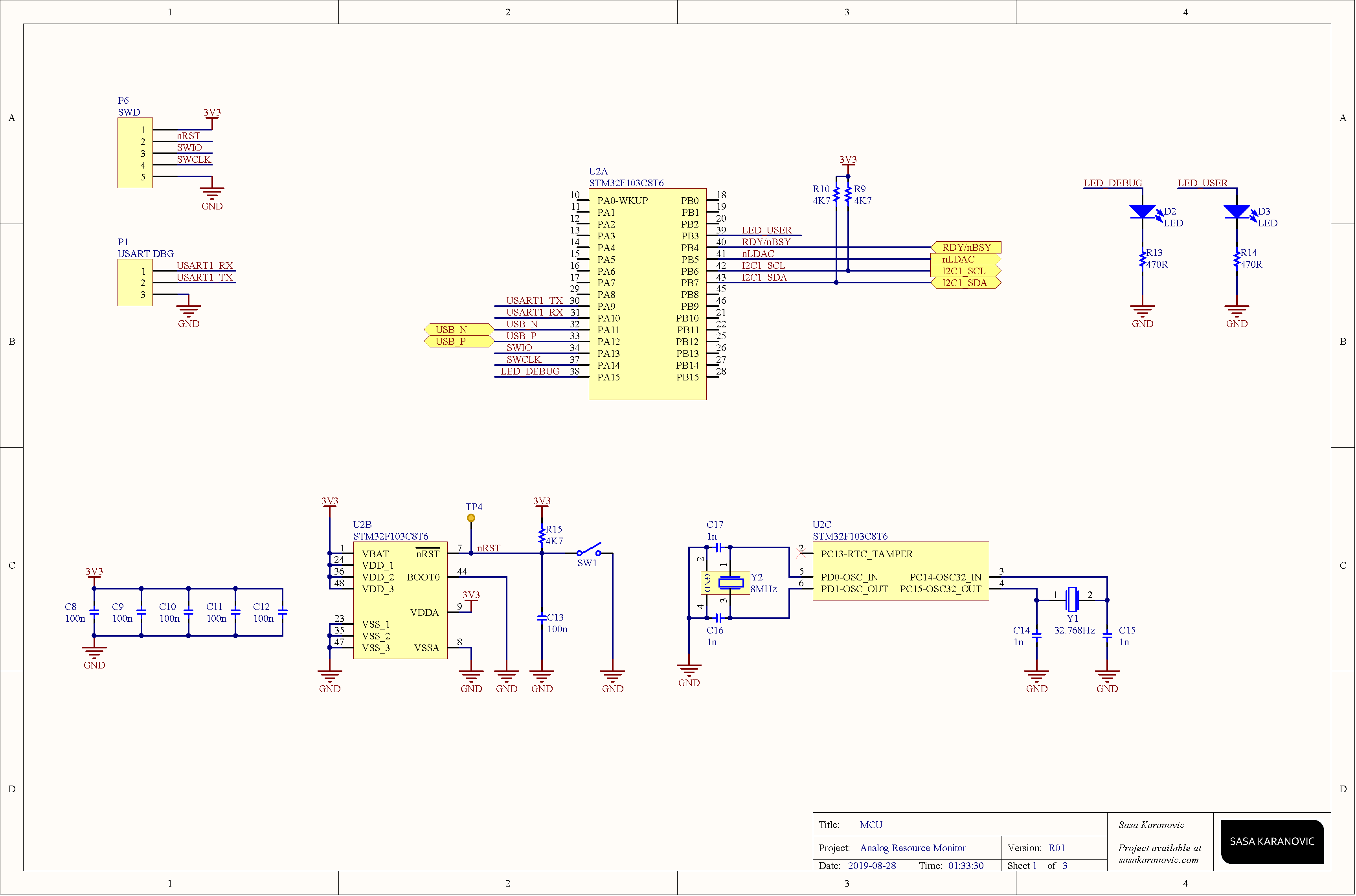
Since I had a bunch of STM32F103 dev boards (both Nucleo/Discovery and BluePill) I used that as my starting point. STM32F103 is a complete overkill for this project, but as I said my picks were based on what I had laying around, for you it might be a PIC, AVR, Arduino or something else.
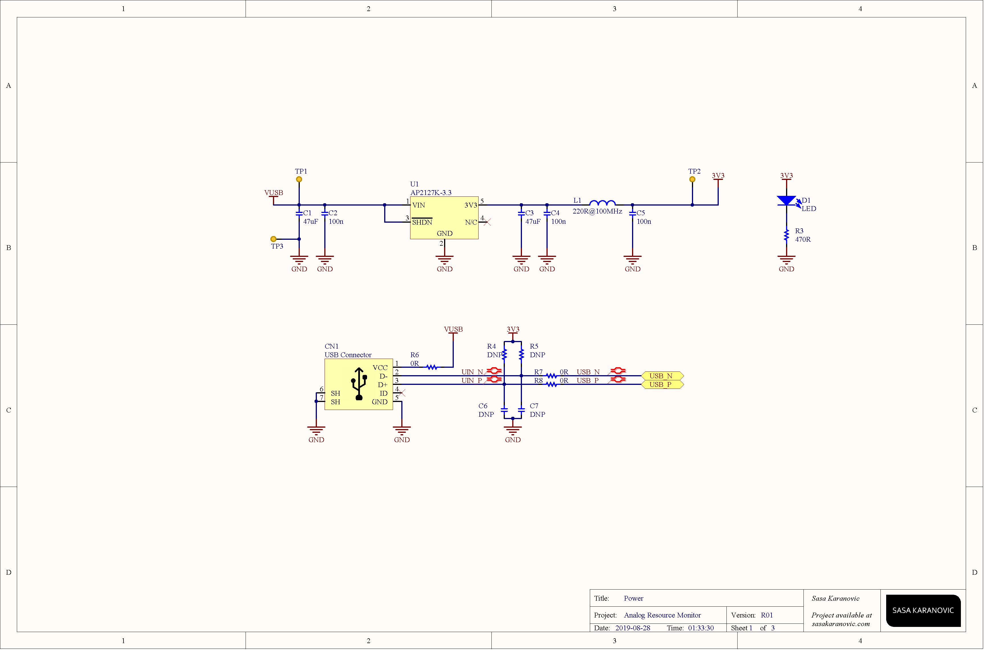
ST32F103 has a built in USB, so I used it to as a CDC device (virtual serial port) to communicate with the device over USB. We could use USB HID or some other USB device type but serial port is probably the easiest one to communicate with from Win/Linux/Mac OS.
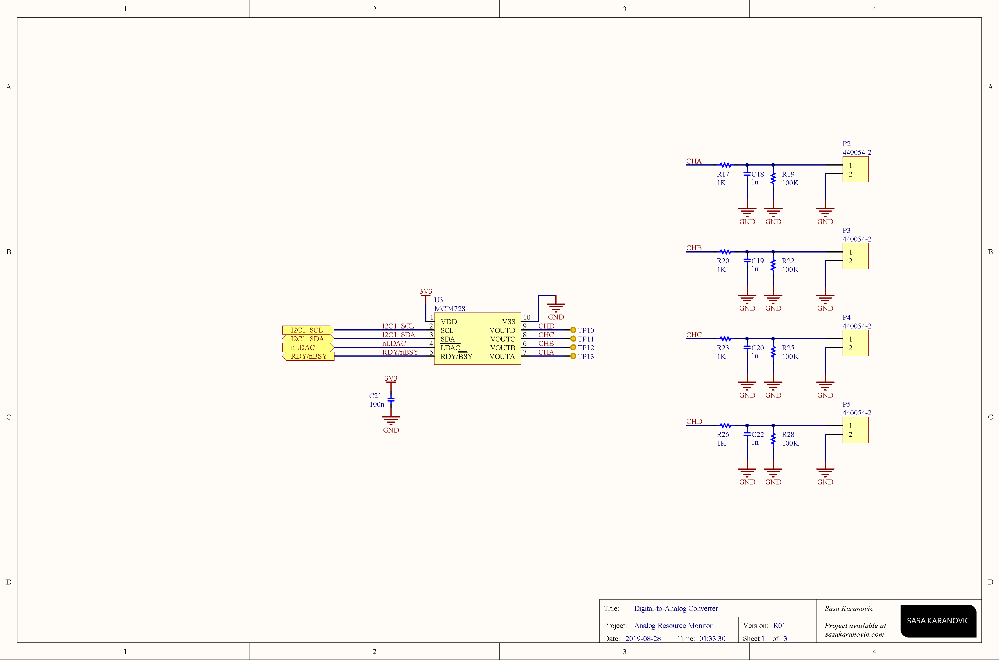
Lastly our MCU communicates with the digital-to-analog converter via I2C bus. Communication is very straightforward, you configure few registers like (gain, voltage reference and etc) and then just keep sending the values for each channel.
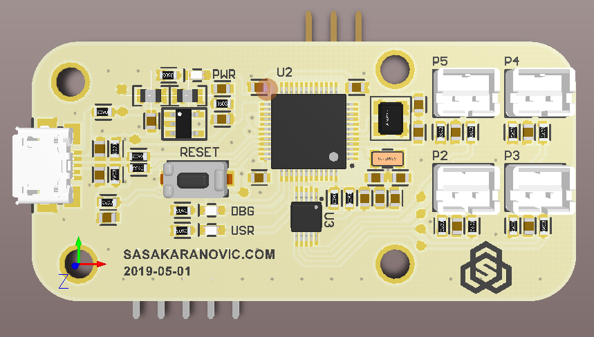
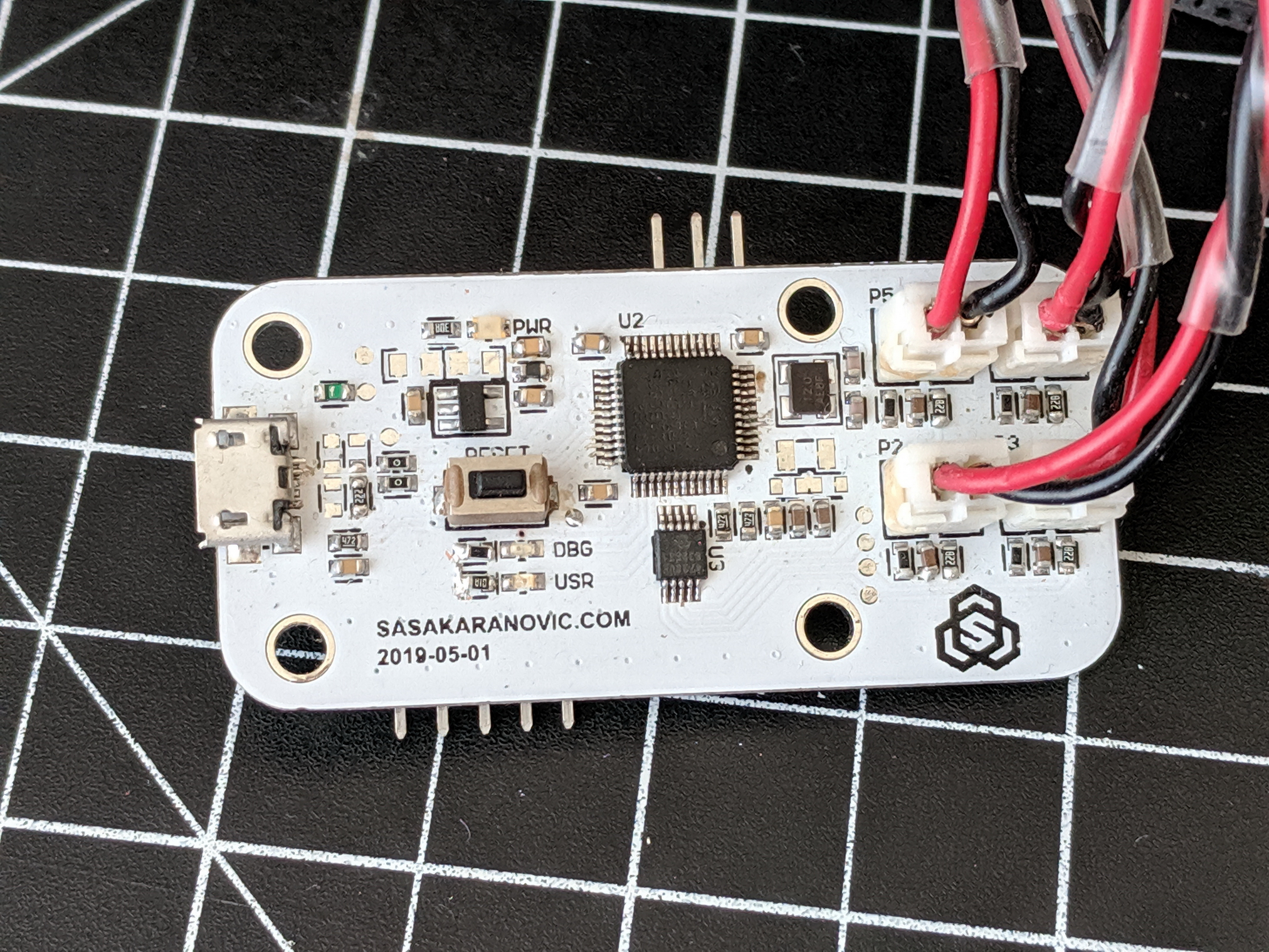
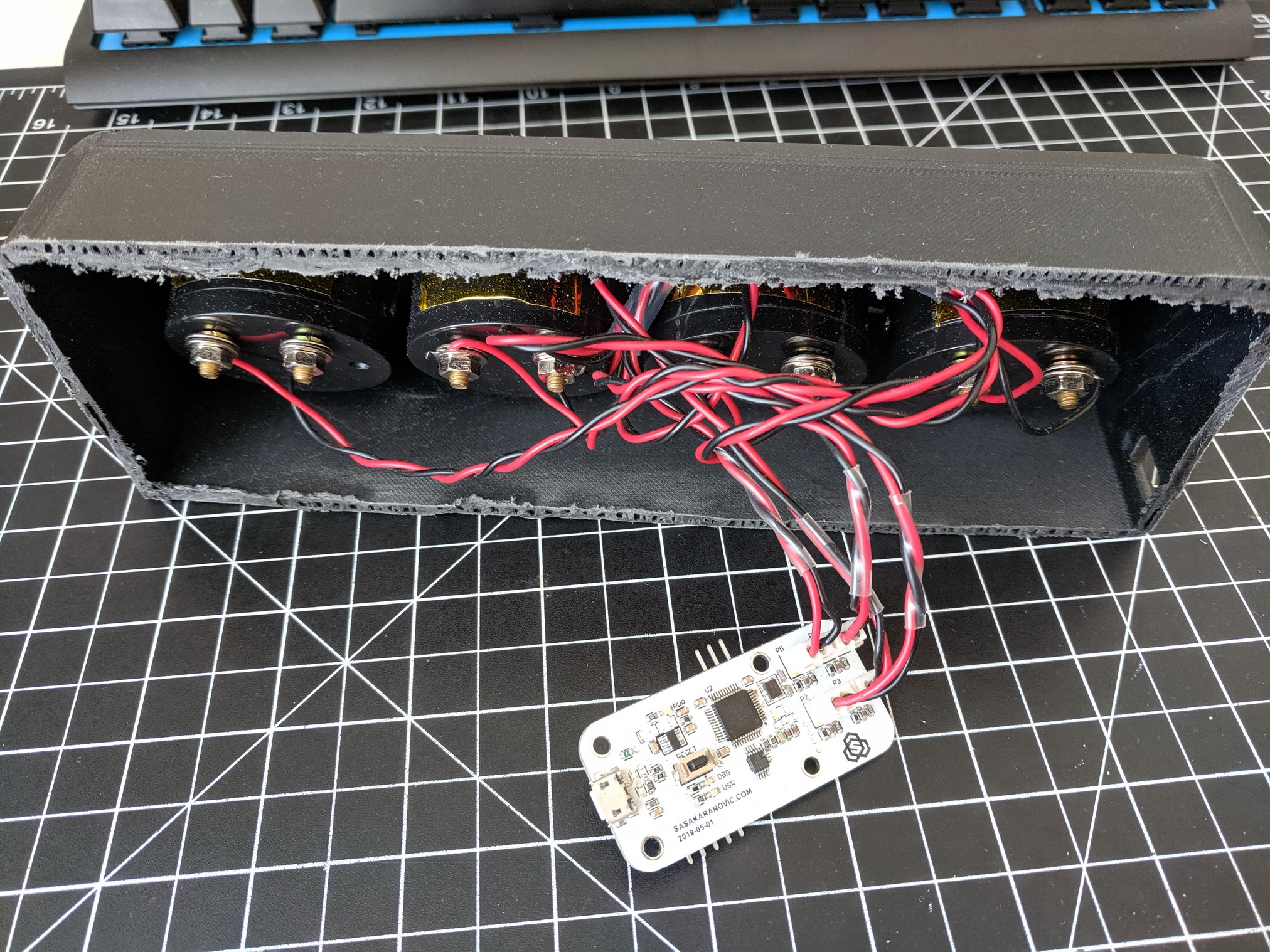
Put it all together, send the board for manufacturing and a week later we have a custom PCB for our project.
Firmware
Entire source code is provided in the GitHub repository but let’s not deep dive into the code, instead we will look at what is happening from a very high level.
#include "board.h"
#include "sys_init.h"
#include "debug.h"
#include "mcp4728.h"
#include "stm32f103_mcp4728_Driver.h"
#include "usb_device.h"
#include "usbd_cdc_if.h"
#include "uart_interface.h"

#define COMM_TIMEOUT    5000    // after 5000ms (5s) of inactivity move dials to zero
volatile uint32_t nCommTimeOutTarget   = 0;
volatile uint32_t miliseconds   = 0;

int main(void)
{
    Sys_Init();
    mcp4728_Start();

    // Loop forever
    while (1)
    {
        // Check if we received new dial values
        if(CDC_ReadyForParse())
        {
            nCommTimeOutTarget = miliseconds + COMM_TIMEOUT;
            parseRxBuffer();
        }
        // If not, check if timeout expired (and reset dials)
        else if(miliseconds > nCommTimeOutTarget)
        {
            mcp4728_analogWriteAll(0, 0, 0, 0, false);
            nCommTimeOutTarget = miliseconds + COMM_TIMEOUT;
        }
    }
}
Firmware is initializing the system at the boot time, i.e. configuring oscillators, setting up USB, I2C, GPIOs, initializing our DAC and other peripherals and after that it enters an infinite loop.
In here, MCU is checking if we received a full packet over a USB CDC, if true, it will call a function to parse the values that we receive and calculate the needed DAC values that we need and then pass them to the DAC itself.
If we haven’t received any new packets, MCU will check if more than 5 seconds have passed without any new messages. In which case we want to return all dials to zero, so we don’t have dials “stuck” at a certain position when you turn your PC off, USB device gets re-enumerated, the application crashes or we lose connection for whatever reason.
Python script for updating values
We now have dials that are modified and ready to go, DAC that is ready to drive them, and also a MCU that is ready to talk to the DAC as well as the host USB. What we need now is a tiny piece of software, in our case a python script, that will read the values for CPU, memory, network and GPU usage and send them to the MCU over serial com port. In the GitHub repository you can find the full script as well as the example for driving the dials via BusPirate or directly by ST32F103/USB CDC.
Instead going through the entire code, let’s just look at the most interesting ones and you can take a look at the full source code
import time, signal, serial, struct
import psutil
import GPUtil

SLEEP_SECONDS = 0.5

# Network usage calc
NET_MBps = 300  # MegaBITS per second, use something like https://speedtest.net to find out
NET_MAX_BPS = NET_MBps * 125000  # bytes per second
g_networkBytes = 0

... (cut) ...

def main():

    global ser
    ser = serial.Serial('COM16', 115200, timeout=0, parity=serial.PARITY_EVEN, rtscts=0)

    CycleDial(5, 0.1)
    while True:
        UpdateGauges(cpu_usage(), memory_usage(), network_usage(), gpu_usage())
        time.sleep(SLEEP_SECONDS)
    exit();

... (cut) ...
We are using psutil module to get the CPU, memory and network usage and for GPU usage we are using the GPutil module. At the beginning there are some definitions that you should change, like
– Your maximum network speed (if you want to measure internet usage vs. network usage)
– Amount of seconds you want the script to sleep after sending a value (smaller number will make dials less laggy but also will hog the CPU more, because of the frequent updates.
– Replace ‘COM16’ with the name of you COM port that your device is connected to.
– CycleDial actually doesn’t do much, it runs at startup to cycles the dials from 0-100 and back to zero with given increments and period but it looks _SO NICE_ when you power up the unit. You will just have to check the video (above, also YouTube link) and see for yourself.
Too long, didn’t read [TLDR]
This is a DIY project or a guide of sorts if you will, on how to build a physical dashboard for your PC. I’ve completed this project a while ago but it’s such a “wide” project involving custom hardware design, custom firmware, 3D printing, some software development and etc. For that reason I pushed off on writing about it until I get it “just right” but eventually I figured it’s better to share it with you nice folks of the internet and add more material or polish the details as you provide your feedback.
Conclusion
This is one of those tiny-big weekend projects; basically there are many tiny pieces that make one “big project” that you spend your entire weekend or two working on.
I had a lot of fun prototyping and building this project and I enjoy looking at it on my desk every day.
I would love to hear your thoughts and suggestions. If you would like to see more projects like this or want me to go into greater detail and explain how this one works, send me a message or drop a comment in the comment section below.
Thank you!
Special thank you to my friend and coworker Brendan Coady ( @bk2coady on Instagram and Twitter) for helping me setup and 3D print the enclosure for this project!
Build your own or see how it works under the hood
As always, all files for this project are available in my GitHub repository.
Are you planning on building your own or this gave you an idea for a project?
Please send your images and videos with me. I always love to see what you made, how you improved or modified this project to your liking.
All of the source files and projects files are provided as open-source open-hardware for you to build on top of or use in your project. While I do not require any credits or attributions, I do like taking credit and attribution so if you think it’s appropriate, feel free to mention me 🙂
Bonus: Previous variants and images from development
Neat idea, and very slick presentation. I’m familiar with how the rest works, but thanks especially for the Python script — always nice to learn how to do something new like pull PC stats.
I did find a typo: You have A2D instead of DAC in a couple of places in the “In a nutshell” section.
This is exactly what I was looking for! I have been tinkering with the idea of building a wooden retro-future PC case and wanted to have backlit gauges as seen on old fashioned radio sets and whatnot to output CPU/GPU/Memory usage and Temperature. If I may be so bold to ask, would you be willing to help me pick out the right parts? I am confident I can figure out the software but my knowledge of hardware (microcontrollers, wiring, gauge types, etc.) is sorely lacking.
Thank you for your time!
Hi Daniel. If you watch the video, it will guide you from the component selection, explaining how they work, what needs to be modified and how to wire everything and get it up and running. Firmware, hardware and software are also provided, so it shouldn’t be hard to copy&paste everything and you should be good to go. Also, in the comments section you can find links to each component that I used.
Keep in mind that there are many ways you can do this, I’ve shown just one of many.
Take a look at the video and if you are still unclear on how to build it, feel free to send me an email with any questions you have and I’ll try to answer the best I can.
Cheers!
Hey let me know if you wanna tackle this project with me! I have been looking to do the same! I want my PC to look like one of those old wooden Zenith radio’s along with analog gauges such as this!
Thank Sasa for the very detailed write-up. I really want to do the same thing but I’m struggling a bit as I know next to nothing about electrical engineering. After some research, I think I’ll be able to get some PCBs printed by JLCPCB easy enough and know which component should be soldered into which position on the PCB.
The last roadblock is about the components.
– The generated BOM is missing the manufacturer/distributor details for designators [C14,…, P6] and [R17, R20, R23, R26]. The BOM says they are 1n capacitors and 1K resistors, respectively, so I figured I can use 06035C102KAT2A capacitors and RC0603FR-071KL resistors since those are the most “similar” parts compared to ones on the BOM.
– STM32F103C8T6 micro-controller is out of stock everywhere. Some Chinese eBay sellers got some for dirt cheap so I’m not sure if they are genuine, or will work at all. Anw, it’s just a DIY project so wouldn’t hurt to try. If you know of a reliable alternative please let me know.
– MCP4728 DAC is also out of stock everywhere so I’ve been looking for an alternative without having to modify the PCB (I wouldn’t know how to do it anw). I’ll probably just buy an Adafruit MCP4728 (it’s a dev board, or whatever it’s called) and desoldered the chip, or find a way to rig it to the PCB.
Worst case scenario I’ll make something similar to the protoboard with an Arduino – not very neet to stuff inside a PC but better than nothing. Hopefully the parts arrive soon so I can start.
Hi Foo,
I’m glad you liked the project. Let me know how it turns out!
STM chips are still out of stock pretty much everywhere. You could look into buying some BluePill development boards and scavenging the MCU from them.
For the DAC, I’m not sure which replacement to suggest that would be pin-to-pin compatible. If you can get an eval board and desolder from it, I would suggest that.
Feel free to reach out if you need help and I would love to see how the finished dials end up looking!
All the best!
Saša
Hi there,
is there a way to split up the cables on the stm32 in 4 and just use 4 MCP4625 modules as DACs?
Hi Marc,
Yes that could work. You could also get a DAC with 4 channels.