 I’m working on a new weekend project that will be released as soon as I finish the Windows application and it will be released as open-source open-hardware project. The uber-cryptic title stands for “Power-supply Active Load tester”.
Recently I was in need for a simple device that will draw reasonably precise amount of current from my power supply unit under test and read the voltage and current draw. There are a lot of schematics and products that do just that, or you can do this just with two digital multimeters, op-amp, mosfet and potentiometer and that will probably work just fine, but I wanted to create my own version and try to improve it. 🙂
[UPDATE]
The project has been released as Open Source Open Hardware and all of the necessary information is located on this page and also on GitHub. 🙂
If you don’t want to hear how I got this idea and why I did this project, you can skip this paragraph. 🙂
I had some weird issues with my Raspberry Pi model B that started to annoy me. It worked just fine until at random point it freezes the device, and I had to power off-on the device to get it started again. After some testing, probing, experimenting I deduced that the cause of this problem is the power adapter. The Raspberry Pi current draw peaked around 300-400 mA, and power adapter can handle that easily, but for some reason (seek more details about drifts in PS units) if Raspberry Pi tries to draw 300-400 mA from the power adapter for longer period of time, the voltage of the power adapter starts to drop significantly. Since I bought cheap 5V 1A power adapter, I was not surprised but that gave me an a idea for my weekend project.
I wanted to make a affordable and reasonably precise device that will be able to:
- Draw constant current from the power supply under test
- Measure current draw
- Measure voltage of the power supply under test
- Data logging and plotting logged data
- Characterization of the power supply that is being testing
- Communicate and be programmed over USB (via USB-to-UART)
- Have an API so that you can read/write data from and to the device easily with 3rd party software
- Device that can be easily upgraded, modded and change to be as versatile as possible for such device
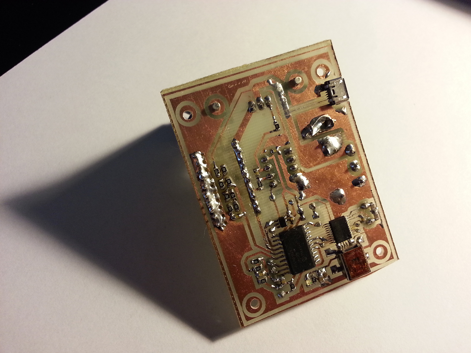
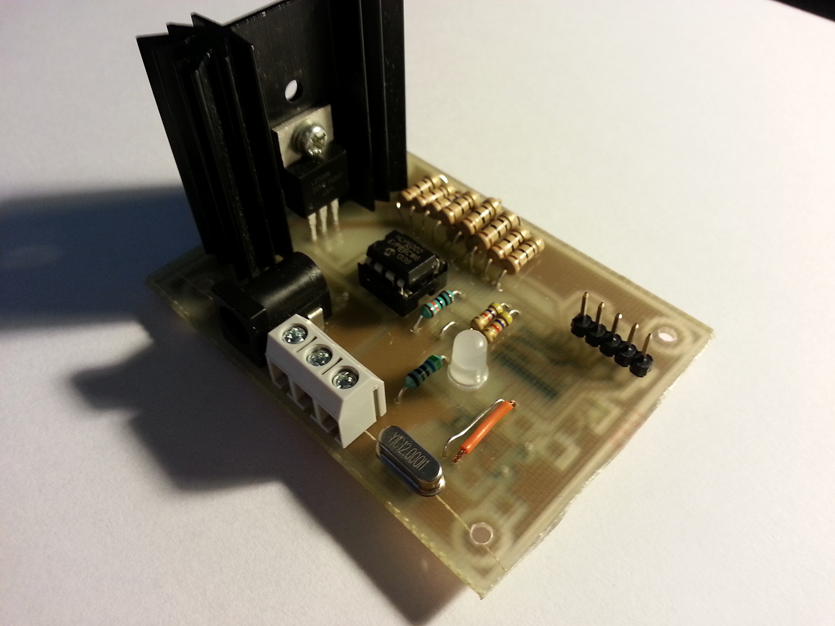 You can see the device schematic below. This is the demo and proof of concept and keep in mind that I’m using the components that I have laying around, although all of the components are easily available. I’ve built my own PCB and tested the device and it works just like I wanted.
PAL Tester Schematic v0.6
What I would greatly appreciate at this point:
I’m experienced programmer and I will create the Windows application that will be able to communicate with the device and the application will be written in vb.net, c# or python. However if you are interested in helping out, you can and in a lot of ways:
- Creating an application for Windows/Unix that to communicate with the device and graph logged data
- Reviewing code on GitHub
- Requesting features and giving suggestions for improvements
- Reviewing the device design
- Spreading the word about this project 🙂
- Suggesting a better name 🙂
- Contribute to this project in any other way you can/want 🙂
If you wish to get more information about this project, please contact me via email, Skype or any other way you find most convenient for you.
Further documentation (API, Schematic, Source-Code, UART communication samples and everything else) is available on request [mainly because I expect it to be tweaked few times before initial public release]
Have a look at the Re:load from Arachnid Labs. $15 for a board that will accept 0-3 amperes of load current (adjustable). Open Source Hardware on Tindie.
Thank you Dawn. I saw Re:load project and also the Pro version which is way way more expensive. 🙂 However this basic Re:load version doesn’t have communication with the PC (as far as I know) or any other way of displaying voltage/current, so you have to measure current/voltage of the power supply unit with two multimeters or panel-meters or some other way. It does the job fine, but if it’s worth doing, it’s worth “overdoing”. 🙂
Device that I have created does the same thing plus many other “useful” things like: it displays the voltage and current draw on your PC. You will be able to select between manual and automatic mode of operation so you can
test the PSU and log it’s performance or automate your tests if you have the need for it. Display the voltage vs. current on a graph so you can see the PSU characteristics. See how PSU works under stress ie. program the device to draw 1A then 0.1A then 1A again in intervals of x seconds or anything else that comes to your mind.
Also I’m using components that anyone can get on the cheap, compile the code using free compiler tools, create a simple PCB so you can fabricate the device at home and many other things.